
Capacitance Formula
Capacitance is how much charge a capacitor stores per volt. This calculator applies the main capacitance formulas: the parallel-plate formula from plate area, gap and dielectric; combining capacitors in series and parallel; the charge and energy stored at a voltage; the RC time constant; and decoding the three-digit codes printed on ceramic capacitors.
- Free to use
- No sign-up
- Runs in your browser
Capacitance calculator
Capacitor Reference Pack
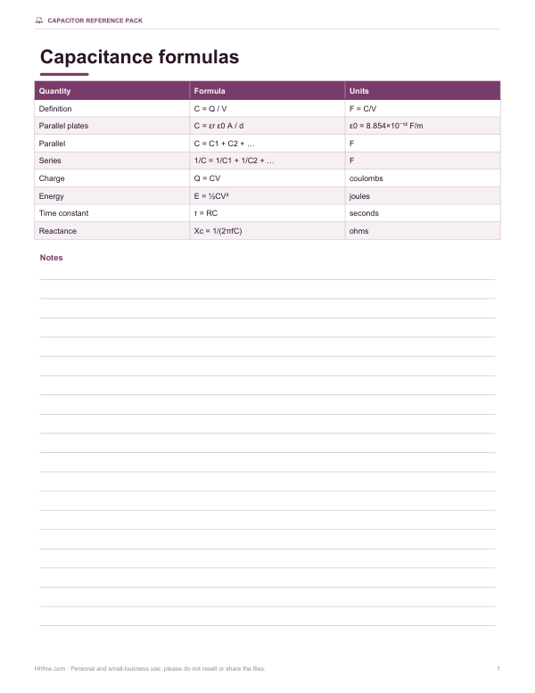
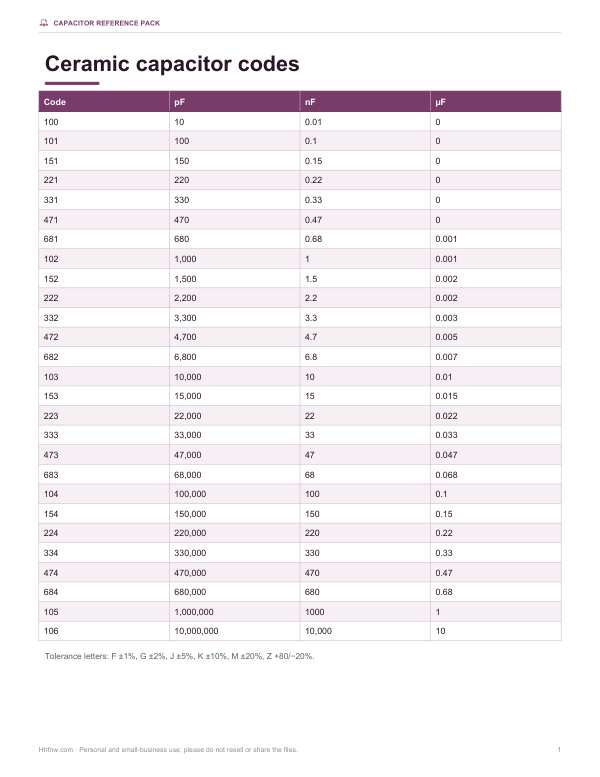
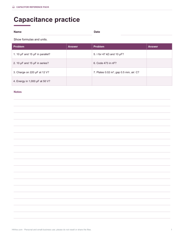
Printable capacitor formula sheet, capacitor code chart (101 to 106 with tolerance letters), dielectric constant table and a practice worksheet with answers.
- Formula sheet (PDF)
- Code chart (PDF/XLSX)
- Practice worksheet (PDF, DOCX)
Formats: PDF, DOCX, XLSX. Instant download after payment (link valid 72 hours, up to 5 downloads). AI-assisted: the templates were drafted with AI help and reviewed and laid out before publishing.
$5.00 USD, one-time 3 files · about $1.67 each
- Instant download
- 7-day refund
- Secure checkout by Stripe
7-day money-back guarantee. Full refund within 7 days of purchase, even after you download.
Full refund within 7 days — see the refund policy and license.
Free printables
Single sheets you can print right now, no sign-up. The full pack adds every sheet in one download plus the editable files.
The capacitance formula
Capacitance is defined as C = Q / V: the charge stored per volt, measured in farads (F). For two flat parallel plates, capacitance depends only on geometry and the material between them: C = εr ε0 A / d, where A is the plate area in square metres, d the gap in metres, ε0 the permittivity of free space (8.854 × 10⁻¹² F/m) and εr the relative permittivity (dielectric constant) of the insulator. Bigger plates, a smaller gap and a higher-permittivity dielectric all increase capacitance.
Formula summary
| Quantity | Formula |
|---|---|
| Definition | C = Q / V |
| Parallel plates | C = εr ε0 A / d |
| Capacitors in parallel | C = C1 + C2 + C3 + … |
| Capacitors in series | 1/C = 1/C1 + 1/C2 + 1/C3 + … |
| Charge | Q = C V |
| Energy stored | E = ½ C V² = Q² / (2C) |
| RC time constant | τ = R C |
| Capacitive reactance | Xc = 1 / (2π f C) |
Series and parallel
Capacitors in parallel add directly, because together they behave like one capacitor with a larger plate area. In series, the effective gap grows, so the total is less than the smallest capacitor: add the reciprocals and take the reciprocal of the sum. For two capacitors in series, C = C1C2 / (C1 + C2). This is the opposite of resistors, which add in series.
Worked examples
- Parallel plates: two 100 cm² plates 1 mm apart in air give C ≈ 1.0006 × 8.854×10⁻¹² × 0.01 ÷ 0.001 ≈ 88.6 pF.
- Combinations: 10 µF, 22 µF and 47 µF give 79 µF in parallel and about 6.00 µF in series.
- Energy: a 470 µF capacitor charged to 25 V holds Q = 11.75 mC and E = ½ × 470×10⁻⁶ × 25² ≈ 0.147 J.
- RC: 10 kΩ with 100 µF gives τ = 1 s — about 5 s to charge almost fully.
- Codes: 104 means 10 × 10⁴ pF = 100,000 pF = 100 nF = 0.1 µF.
Reading capacitor codes
| Code | Value |
|---|---|
| 101 | 100 pF |
| 102 | 1 nF (1,000 pF) |
| 103 | 10 nF |
| 104 | 100 nF = 0.1 µF |
| 105 | 1 µF |
| 222 | 2.2 nF |
| 472 | 4.7 nF |
| 473 | 47 nF |
The first two digits are significant figures and the third is the number of zeros, in picofarads. A letter after the code gives tolerance: J = ±5%, K = ±10%, M = ±20%. Electrolytic capacitors usually print the value and voltage directly, such as 470 µF 35 V.
Dielectric constants
| Material | Relative permittivity εr (approx.) |
|---|---|
| Vacuum | 1 |
| Air | 1.0006 |
| PTFE (Teflon) | 2.1 |
| Polyester (PET) | 3.2 |
| FR-4 circuit board | 4.3–4.7 |
| Mica | 5–7 |
| Ceramic (X7R class) | hundreds to thousands |
| Water | about 80 |
Charging and discharging
When a capacitor charges through a resistor, its voltage rises quickly at first and then more slowly: after one time constant (τ = RC) it reaches about 63.2% of the supply voltage, after two about 86.5%, after three 95%, and after five about 99.3%, which is usually treated as fully charged. Discharge follows the same curve downwards. These curves are the basis of timing circuits, debounce filters and the smoothing of power supplies.
Choosing a capacitor type
| Type | Typical range | Uses |
|---|---|---|
| Ceramic (C0G/NP0) | 1 pF – 10 nF | Precise, stable filters and oscillators |
| Ceramic (X7R, X5R) | 100 pF – 100 µF | Decoupling and general purpose |
| Film (polyester, polypropylene) | 1 nF – 10 µF | Audio, timing, snubbers |
| Aluminium electrolytic | 0.1 µF – 100 mF | Power supply smoothing (polarised) |
| Tantalum | 0.1 µF – 1 mF | Compact, stable bulk capacitance (polarised) |
| Supercapacitor | 0.1 F – 3,000 F | Energy backup and buffering |
Ranges are typical and vary by manufacturer. Always check the voltage rating, and note that many ceramic capacitors lose a large part of their capacitance at high DC bias.
Capacitive reactance
In AC circuits a capacitor’s opposition to current falls as frequency rises: Xc = 1 / (2πfC). A 1 µF capacitor has a reactance of about 2,653 Ω at 60 Hz but only about 159 Ω at 1 kHz. That is why capacitors pass high frequencies and block DC, and why the cut-off frequency of an RC filter is 1 / (2πRC).
Safety note
Large capacitors can store dangerous energy long after power is removed — especially in power supplies, microwave ovens and camera flashes. Discharge capacitors safely with a suitable resistor before handling, never exceed the rated voltage, and observe polarity on electrolytic capacitors.
Privacy
All calculations run in your browser; nothing is uploaded.
Frequently asked questions
What is the formula for capacitance?
C = Q / V; for parallel plates, C = εr ε0 A / d.
How do capacitors add in series?
Add the reciprocals: 1/C = 1/C1 + 1/C2 + …
How do capacitors add in parallel?
Simply add them: C = C1 + C2 + …
What does 104 mean on a capacitor?
100 nF (0.1 µF).
How much energy does a capacitor store?
E = ½ C V².
What is an RC time constant?
τ = R × C, the time to charge to about 63% of the supply voltage.
What is a farad?
The capacitance that stores one coulomb of charge at one volt; practical capacitors are usually measured in pF, nF or µF.
Why is series capacitance smaller?
Series capacitors behave like one capacitor with a wider gap, which lowers capacitance.
What is the unit of ε0?
Farads per metre (F/m); its value is about 8.854 × 10⁻¹² F/m.
Does capacitance change with voltage?
Ideally no, but many ceramic capacitors lose capacitance at high DC voltage.
Why do parallel capacitors add?
Together they act like one capacitor with a larger plate area.
Can I mix units like µF and nF?
Yes, type values with their prefixes, such as 4.7u, 470n and 100p.
Is anything uploaded?
No, it runs in your browser.